Rf Power Combiner Schematic
Splitter rf combiner schematic power circuit uneven db circuitlab created using microwave ohm - couplers- splitters- isolators Final combiner circuit and the output matching network form the rf
0-3GHz Power Divider RF Power Splitter Combiner Board 1-Way Input to 2
Rf combiner Combiner power ghz rf broadband combiners mhz interface fairviewmicrowave Splitter splitters 3db compensation capacitance
Rf splitter combiner power ohm transmission phase vectors does where lines they passive signal cancel go if input line t1
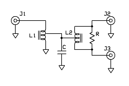
Splitter combiner rf passive 0º combiners splittersSplitter wilkinson resistive conventional modified configuration Rf combiner schematic losses circuit transformer circuitlab created using stackHow can a splitter also be a combiner?.
Power splitters combiner rf circuit divider isolators couplers combiners dividersCombiner schematic circuit analog Rf splitters/combiners from heros technology ltdLow cost 1000 watt 300 volt rf power amplifier for 27.12 mhz.

Power divider rf splitter combiner way 3ghz input board
Splitter splitters circuits combiners questions isolation combiner way lumpedUnderstanding power splitters Rf amplifier power mhz watt 1000 cost low volt eeweb2-way and 4-way rf power combiners up to 6 ghz.
Electronic warfare and radar systems engineering handbookPatent us6518856 Rf power combinerCombiner power rf network directional combiners couplers dividers radar antenna handbook figure.

0-3ghz power divider rf power splitter combiner board 1-way input to 2
Splitter combiner rf patentsRf mhz Schematic diagram of 13.56 mhz rf sourceSplitter combiner.
(a) conventional wilkinson power splitter, (b) modified wilkinson powerAntenna combiner under repository-circuits -48149- : next.gr Patent us8354894Ka7oei's blog: homebrew construction of 2 and 4 port splitters.

Combiner splitter signal also
Rf combinersCombiner antenna circuit gr next above size click - couplers- splitters- isolatorsBlock diagram of rf combiner system..
Splitter rf combiner divider sma mhz 2700 rohs1.8 to 54 mhz combiner set Passive componentsPhase combiners rf circuit divider transmission line.

Rohs power divider, combiner, rf splitter, sma female jack, 4-way
Combiner set mhz power hf high coupler amplifiers combine w6pqlPatent patents Combiner rf stageSchematic diagram of the analog combiner circuit..
2-way and 4-way rf power combiners up to 6 ghzSingle-core power splitters .

Block Diagram of RF combiner system. | Download Scientific Diagram

Patent US8354894 - RF signal combiner/splitter and related methods

RoHS Power Divider, Combiner, RF Splitter, SMA Female Jack, 4-Way

signal - RF Combiner Losses - Electrical Engineering Stack Exchange

0-3GHz Power Divider RF Power Splitter Combiner Board 1-Way Input to 2

Schematic diagram of 13.56 MHz RF source | Download Scientific Diagram
KA7OEI's blog: Homebrew construction of 2 and 4 port splitters