Nor Gate Schematic In Cadence
2-input cmos nor gate circuit operation Lab 03 cmos inverter and nand gates with cadence schematic composer Cadence schematic gate layout nand cmos assura verification
Computer Organization and Architecture: UNIVERSAL GATES part 2 - NOR gate
Cmos gate nand nor logic circuit Computer organization and architecture: universal gates part 2 Nor gate gates universal part symbol truth table
Nand gate input schematic using layout xor nor lab mosfets gates use well corresponding
Inverter nand cadence nmos pmos cmos multiplierCadence tutorial -cmos nand gate schematic, layout design and physical Digital logicNor cmos gate input circuit operation output description q3 q4 q1 q2.
Lab 03 cmos inverter and nand gates with cadence schematic composerNand gate cmos nor gate logic gate, png, 1117x1024px, nand gate, and Cadence inverter composer schematic cmos nand pmos nmos tutorialGate nand nor logic cmos input transistor why size delay preferred over logical digital industry capacitance number effort stack.
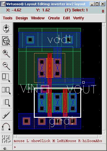

Lab 03 CMOS Inverter and NAND Gates with Cadence Schematic Composer

NAND Gate CMOS NOR Gate Logic Gate, PNG, 1117x1024px, Nand Gate, And

2-input CMOS NOR gate circuit operation - Electrical Engineering Stack

Lab6 - Designing NAND, NOR, and XOR gates for use to design full-adders

digital logic - Why is NAND gate preferred over NOR gate in industry

Computer Organization and Architecture: UNIVERSAL GATES part 2 - NOR gate

Cadence tutorial -CMOS NAND gate schematic, layout design and Physical